If you're having an issue with your power jack, contact us at sales@ogotoilet.com. Our customer care will make sure you get the right part to get your OGO™ working properly again.
What You’ll Need
-
Replacement 12V DC barrel jack
-
Wire strippers or utility blade
-
Flathead (optional) for WAGO® clip release
How to Replace the Jack
1. Disconnect Power
Unplug the unit from its 12V DC power source.
2. Access the Power Jack
Reach inside the housing and push the jack out from the panel.
Most versions are pressure-fit or secured with a nut you can turn by hand.
3. Disconnect Wiring
-
If your jack is wired into a WAGO® connector, press the orange tab and pull the wires free.
-
If wires are wrapped or shrink-wrapped, gently separate them and expose the individual red and black wires.

4. Remove the Old Jack
Once wiring is disconnected and the jack is loose, pull it fully out through the front panel.
5. Prep the Wires
-
If your replacement jack doesn’t come pre-wired, you’ll need to attach your own wires.
-
Strip back the outer plastic coating if needed to expose the red and black wires inside.
-
Then strip about ¼" off the ends to make clean connections.

6. Connect to the New Jack
-
Match wire colors: Red to +12V, Black to Ground
-
Insert wires into the WAGO® clip and secure by closing the orange clip.
7. Install and Test
-
Seat the jack back into the panel opening.
- Tighten the bolt around the jack by hand then secure with wrench. Do not over torque.
-
Plug the unit into power.
-
Check for function: fan turns on, button triggers cycle, LED lights up.
Wiring Diagram
Our wiring has changed over the years as we continue to optimize our products. If you need a previous version of a wiring diagram, you can find it here or reach out and customer care can help get you the correct one for your unit.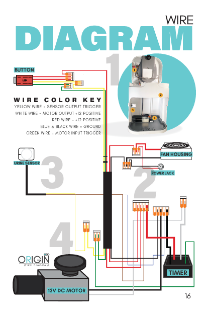
Wiring Colors:
-
Red = +12V
-
Black/Blue = Ground
-
Yellow = Sensor trigger
-
White = Motor +
-
Green = Motor trigger